
Sometimes we need to put a robot in our sci-fi theme artwork, but you do not usually draw robotic or mechanical things. In this tutorial, I will show you an easy way of designing a humanoid robot and drawing with clip studio ruler tools.
Process Overview
Video Tutorial
The basic concept of a humanoid robot design
There are several things that you need to know before designing a humanoid robot.
Here are the 3 main keys for starting your design.
>>Figure design
The humanoid robot is a robot that has a frame like a human body. Its main composites are body parts and joints.
When turning it to robot parts, draw it as boxes.
By adjusting the box parts, you can easily design the robot scale.
For example :
If you are going to design a robot that looks like it belongs in the front lines, make the chest and arms bigger to smack the enemy with or to carry a weapon with.
Or thinner and smaller body for a robot working in a laboratory so it can move freely in limited space.
Or a bigger head for a cuter robot that contains a lot of information :D
You can also adjust parts and joints positions to create a more unique style.
Note: you have to give more attention to the robot’s movement when reducing some joints if you need to make a more realistic looking robot. For example, the robot can’t walk correctly if you remove its knee joints. You may add some wheel or power engine at its feet to float.
>>Body parts
Mainly the robot parts are a solid shell that covers the robot mechanical insides. So its shapes can be whatever you feel like to fit the design, such as boxes or cylinders.
You can also put the parts without shells but instead with a skeleton structure.
>>Joints
For the robot design, you can find some references to mechanical joints to design your own type of joints, here are some examples of joints.
In some parts such as the spine it may need continuous joint parts.
Or covering for protection, such as shoulder parts or elbows.
Note that there’s also some limitations to the movement of each joint. (except the ‘no joint’, it is futuristic technology no one knows what it’s going to be, so you can put anything you want)
Also note that the more realistic you make the joints, the more realistic your robot will be!
Working on design
In this part I will show you the process of designing a humanoid robot and draw it out with Clip studio.
>>Design the parts
Plan the robot body figure and then add some simple joints
Usually, the robot’s body is symmetrical for the balance in movements, but you can also design non-symmetrical robot’s too, there is no strict rule on that :D
Then use the Symmetrical ruler to draw the details.
Select the menu ‘Symmetrical ruler’ in the ruler subtool, then adjust [Number of lines] to 2 and have the [Line Symmetrical] checked.
Drag the line on the middle body of the robot, hold [Shift button] to make it perfectly vertical-align to the image.
Check on the option [Show in all layers] in the layer panel, this will allow it to appear on all the layers.
Now you can draw on one side and it will appear on the other side.
I use simple pen for the shape sketch
Start by drawing the rough shape of the robot, then apply the details later.
Tips: when working with the Symmetrical ruler, you can’t use the eraser tool to erase on both sides.
Use transparent color instead! You can select it below the color panel and paint with your current brush.
Now it’s possible to erase on both sides!
Optional: draw the side designs for a clearer image to your design
Tip: put the line projected from the front view to easily control the scale of the sketch.
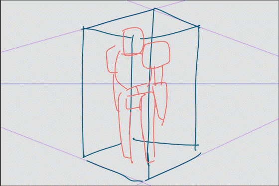
>>Draw it in perspective
If you’re always messing with the perspective( like me =w= ), learning how to use [Perspective Ruler] will change your life forever!
However, you also need to learn some basics of how the perspective takes effect in the drawing.
It is just like looking at an object in a box. Imagine a box covering an object.
When you drag the project line from the box, it will add vanish points somewhere. (it may stay outside of the image don’t worry about it)
When you draw the box, cover the object. You will understand more about perspective, you can give it a try on any image of some object. Take a photo with your phone and practice.
(Note: using a polygon shaped object will be easier than a curved object.)
Select the perspective ruler at [Add vanish point] process, then drag the ruler to the vanishing point of the box.
You must drag another line to commit the perspective ruler
Clip studio will automatically add the horizon line (and ruler on the layer) for the perspective ruler.
Draw another perspective ruler for another vanishing point, and you’re done with the ruler.
Simplify the shape of the design and place on the canvas with the perspective ruler.
Transform the image : Edit > Transform > Free Transform [CTRL+SHIFT+T]
Set the mode to [Free Transform]
Then move the corner of the transform box to fit the ruler at one side.
Create a new vector layer for the box sketching
I recommend using the ‘fill-in-mono pen’ to draw the box because it will give the pen no pressure as if you’re drawing a blueprint.
I love to start with the feet because they’re the nearest to the ground line we made.
In eraser property, you can find the [Vector Eraser] option that makes it easy to work with the unwanted lines.
Draw the more box by using the sketch as a reference to project the line.
Then draw another line to complete the boxes. The perspective ruler makes this process very easy!
Clean up unwanted lines each time the part is finished.
Tips: use different colors to make drawing easier, these box shapes are just for drawing references, don’t worry if they are not perfect.
Disabled the snap to ruler
Draw the parts in the reference box, this will make it easier to manage the perspective of the robot.
Draw the parts before adding the joints.
Also, use different colors to avoid confusion.
When it’s done, change the ink color to the same color
(lock the layer transparent then fill with color)
>>Inking process
For the inking process, I simply draw with the ‘Bezier Curve tool’ which is located in ‘Figure Sub tool’
Create a new vector layer, the bezier line is only editable on the vector layer.
And draw it on the sketch we made
Controls for Bezier curve tool:
Click = make corner node (square node)
Click, hold and drag = make a curve (circle node)
Double Click = stop the line
Both nodes have arms control so that you can pull to adjust the curve of the line that is connected to the node.
For more details about the Bezier Curve tool, check my previous tutorial on working with it.
Note that there will be some parts that show the thickness of the parts, make sure you also draw those.
Use the vector eraser to clean up the overlapped part for each part finished, this will help avoid confusion.
You can also edit the line by using the ‘Control point tool’ in ‘Correct line’ subtool
It’s useful to edit parallel curves for part thickness
Finished ink work.
>>Coloring
Coloring the mechanical parts is easy.
Imagine how the box takes effect with the light.
Create a raster layer below the ink vector layer
Draw the line for shading with gray color, use the box for reference.
Then fill the color with the ‘Fill tool’
Also add shadows to the parts that overlap.
Now the robot will look more dimensional.
You can also change the ink color with the object tool
To fill the base color, set the ink vector layer to [Reference Layer]
And in the fill tool, set the Refer multiple to [Reference Layer]
Fill the color in the layer below the shadow, the color will also fill without taking effect from the shadow layer.
(lower the shadow layer’s opacity to see it transparent)
Fill all the color,
Then change the layer mode of shadow layer, to make it blend together with the robot.
(I always use [Linear burn], but you can choose whichever fits your art style more)
Adjust the opacity down until the result are good for you.
There will be some parts that appear under the robot’s shell. Fill it with a darker shade of the parts color.
When you are done with the color fill, make a folder to put it in for easier management.
Optional: I use the ‘Blur tool’ to soften the shadow border a bit on some parts.
And paint additional shadows with the same gray color used in the shadow layer.
Clipping the shadow layer with the color folder will allow it to show on colored areas only.
Before
After
(the overflow gray is gone)
You can also clip many layers in case you have a lot of shadow layers.
For the highlight, create a clipping layer to part color.
And paint with the soft airbrush
(I really love this process because it's like we’re doing the coloring of a toy model.^ w ^/)
On pointy corners, to make it pop up, erase some of the airbrush color on one side of the area
Then blend it with the blur tool to give it a more dimensional look.
Also additional shadows on some parts.
To give it a metallic look to some parts, add the bold highlight effect at the most pointy areas.
To make the robot look shinier,
create a new layer above the ink layer and apply highlights to the borders with a pencil tool and lighter color.
For highlighting the edge areas, hold [Shift] button to drag the straight line
Also give some highlight to top edge of thickness edge.
Big highlighting will give it a shinier look!
finish!
>>Additional customizations
We may add some details to enchant the robot’s looks, such as painting, some dirt and light
For the painting: Type the numeric code, or import some logo.
If it’s typing, rasterize the layer.
Then use the free transform mode [Ctrl+T] to adjust it to the surface.
And paint on with the textured airbrush with transparency on the edge to make it look like ruined painted.
You can also add dirt effect with the texture airbrush and blur tool
And adjust the layer blending mode for a more neutral look (here I used color burn mode)
Optional: Paint scratches and use the textured airbrush ruin the color.
For the spotlights: draw the light from the light bulbs with the color you prefer.
Then paint the dark light(in blue) with [Color burn] layer mode.
And [Add(Grow)] layer mode and paint again to make the light effect.
Tip: add the highlight border to make some parts that have similar colors look separated.
Finish!
Now you can bring the robot to your scene!
(Note : the background here is mix of clip studio image materials)
I hope this tutorial give you some ideas for working with perspective and drawing an easy humanoid robot design with useful tools from clip studio ^ w ^
[Artist's side note]
I have studied about robots in my engineer class at the university and my first job. So I actually made some robot hardware in real life but I am always not good at drawing it. However, since I know the perspective ruler tool, I found the machine is very easy to draw with the tool!!
Users who liked this post


Comment