HOW TO CREATE A BACKGROUND USING PERSPECTIVE
INTRODUCTION
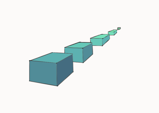
Perspective Drawing is a technique used to represent three-dimensional images on a two-dimensional picture plane.
There are three aspects to perspective. The first has to do with how the size of objects seems to diminish according to distance: the second, the manner in which colors change the farther away they are from the eye; the third defines how objects ought to be finished less carefully the farther away they are.

Perspective drawing can be in one -point, two - point, or three - point perspective.
STEP 1 - Elements of Perspective Drawing
There are two main elements in perspective drawing:
• Linear Perspective; which deals with the organization of shapes in space.
• Aerial Perspective; which deals with the atmospheric effects on tones and colors.
These elements combine to create this convincing illusion of three dimensions on a two dimensional plane.
Two - dimensional plane comprises of two subplanes;
• The Picture Plane; which is the flat two-dimensional surface on which we draw or project an image in perspective and,
• The Ground Plane; which is perpendicular to the picture plane. It is the grey surface on which the shapes appear to be standing and shadows cast upon it. It starts at the bottom of the picture plane and stretches back to the horizon.
The Horizon, which is the viewer's eye - level is the axis around which a perspective drawing is constructed. It is used to scale and distant objects in the field of view implying that they all are the same in height and are standing on the same plane, thereby making good visual sense to the viewer.

For Linear Perspective element take effect, construction lines are used in perspective drawing. These lines are;
• Orthogonal lines and,
• Transversal Lines
Orthogonal lines are parallel to the ground plane and move back from the picture plane thereby meeting at a vanishing point on the eye level. set the varying heights or widths of a rectangular plane as it recedes from view. Vanishing Points are points on the eye-level where parallel lines seem to converge and disappear.
Transversal Lines on the other hand, are perpendicular (right angles) to the orthogonal lines. They are parallel to the picture plane and to one another establishing a fixed height or width between two orthogonal lines. They also form the nearest and furthest edges of a rectangle as it recedes from view.

STEP 1 - One Point Perspective
One point perspective is the simplest method of perspective drawing which uses a single vanishing point. Here, the front and back transversal planes of the object always remain parallel to the picture plane. Only their scale changes as they recede into the distance.

To draw a block in one-point perspective,
Create a vector layer.
Define the eye-level on the picture plane which separates the ground plane and the horizon.
Go to the Layer menu > Ruler-frame > Create Perspective Ruler.
As the Create Perspective Ruler dialog appears, check 1 Point Perspective and hit Ok.
Use the pen tool and draw the four orthogonal lines which meet at a point on the eye-level.
Proceed to drain a rectangle cutting across the orthogonal lines and create an inner rectangle also.
Erase any unwanted lines as a hollow block in one-point perspective is created. These rectangles form the transversal lines.
Add another middle rectangle to add thickness.
Add tones and shadow to make it look realistic.
Draw a Square base with a diagonal which defines the diameter of the circle.
Add the next diagonally using the straight line in the Figure tool turning the perspective ruler off.
Next, turn the perspective ruler layer on and then use the pen tool to complete the grid.
Still on the figure for I select Ellipse and checking the Aspect type checkbox and turning Specify Length in the tools property.
Place the cursor at the edge of the grid, then click and drag across the diagonal to the next edge.
Projects the square edges downwards then create another square below the first one.
Complete the grid and construct another ellipse following the steps above.
Connect the two ellipses using two projection lines.
Erase unwanted projection lines to make the cylinder stand out.
Add tones and shadow to make it look realistic.
STEP 2 - Two Point Perspective
Two point perspective uses two sets of orthogonal lines and two vanishing points to draw an object.
In establishing a Two Point Perspective to draw a box, we rotate the angle of the receding orthagonal lines thereby making no parallel lines to the picture plane while the vertical transversal lines are still drawn parallel to one another and at right angles to the ground plane.
To avoid such perspective becoming awkward or extremely foreshortened, we place the second vanishing point outside the frame of the picture.

To demonstrate the steps on how to draw an object in two - point perspective is similar to one - point type only that the ruler's orientation needs to be followed.
STEP 3 - Three Point Perspective
As the name implies, Three Point Perspective uses three sets of orthogonal lines and three vanishing points to draw an object. It is the most complex form of perspective drawing and is most commonly used when drawing buildings viewed from a low or high eye-level as it would be used in creating our final illustration of this lesson. It naturally suggests the scale of a tall building.
In Three Point Perspective, the vertical transversal lines, which were parallel in one and two point perspective, now appear to recede forming a third set of orthogonal lines arising from the ground plane and eventually meet at the third vanishing point high above the picture plane. In addition, the picture plane seems to be set at an angle as the viewer tends to tilt his/her head forward to look down from the eye level. Vice versa, the process of perspective projection of lines is reversed if viewed from low eye - level.


STEP 4 - Perspective of Circle and Cylinder
The perspective drawing of circles and ellipses follows the same technique we use for constructing rectangles.
There are two steps in creating circles and ellipses in perspective:
• The circle is first visualized in plan form on a flat square grid. Each section of the grid contains one quarter of the circle.
• The square grid is distorted according to the laws of perspective. The circle is then redrawn onto the distorted grid to create an ellipse.
As for cylinder, it is simply a circle which is projected vertically from the ground plane into three dimensions making the ellipse that outline the cylinder are all the same width. However, the roundness of their curves gradually increases as they rise above or drop below eye level. If the cylinder is being projected horizontally from the picture plane, the circular curves that form the cylinder are all the same shape, but their scale reduces as they recede from the picture plane towards the vanishing point.

To draw a cylinder in perspective:
Go to the Layer menu > Ruler - Frame > Use perspective ruler > 3 point perspective
Adjust the rulers using the object tool and click and hold the handles making sure the second and third vanishing points are outside the frame of picture.
Use the pen tool and draw a square base with a diagonal which defines the diameter of the circle following the orientation of the rulers.
Add the next diagonal by using the straight line in the Figure tool. This can be achieved after turning off the layer of the perspective ruler since the figure tool to be applied does not follow the perspective orientation in angle and distance.
Next, turn on the perspective ruler and use the pen tool to complete the grid.
Still on the figure tool, select Ellipse checking the Aspect type checkbox and turning on Specify Length in the tool property.
Place the cursor at the edge of the grid and carefully click and drag extending across the longer diagonal to the next edge by clicking and releasing the pen or mouse button.

CONCLUSION
In conclusion, we intend to use the knowledge of perspective elements and three - point perspective in high eye - level to draw a few blocks of buildings in an urban center. The main recipe material is the construction of squares using the grid system. It is used here to show arrays of similar objects like the windows etc which become thinner as they recede in view.
Also, additional rulers are added to conform with some structuring aside the basic three - pont perspective.
Thanks for viewing.


Comment