HOW TO CREATE A SCENE IN ISOMETRIC USING CSP
INTRODUCTION
Isometric drawings are a type of pictorial drawings that show the three principal dimensions of an object in a single view. The principal dimensions are the overall sizes for the object along the three principal directions. Pictorial drawings consist of visible object faces and the features lying on the faces. The internal features of the object are largely hidden from view. They tend to present images of objects in a form that mimics what the human eye would
see naturally. They show images that bear physical resemblance to the real or imagined object. Pictorial drawings are excellent starting point in visualization and design and are often used to supplement multiview drawings.
An isometric drawing is one of three types of axonometric drawings. It is created on the basis of parallel projection technique. The three principal axes make equal angles with the image plane. In dimetric drawing, two of the three principal axes make equal angles with the image plane while in trimetric drawing, the three principal axes make different angles with the image plane. Isometric drawings are the most popular and are easier to construct than the others.
STEP 1- Terminologies
The nearest edge of the cube to the viewer appears vertical in the isometric view. The two receding axes project from the vertical at 120 degrees on the left and right sides of the vertical line. The three principal axes are therefore inclined at 120 degrees and are parallel to the cube edges in the isometric view. The two receding axes are inclined at 30 degrees to the horizontal line while the vertical axis is at 90 degrees to the horizontal line. These three principal axes are known as isometric axes.

The three visible faces of the cube are on three planes called isometric planes or isoplanes. These isoplanes are called left, right, and top isoplanes. The front view of objects is commonly associated with the left isoplanes, the right view with the right isoplanes, and the top view with the top isoplanes.

The lines an object parallel to the isometric axes are referred to as isometric lines while lines not parallel to them are known as non-isometric lines. isometric projection is a true or accurate representation of an object on the isometric scale, that is, when measurement is made along the isometric axes. Hence, the actual images of object shown in isometric views are called isometric drawings.

STEP 2- Types of Isometric Drawings
Isometric axes can be positioned in different ways to obtain different isometric views of an object. Three basic views are in general use and they are regular isometric, reverse isometric and long-axis isometric views.
In regular isometric, the viewer looks down on the object so the top of the object is revealed. The receding axes are drawn upward to the left and right at 30 degrees from the horizontal. The nearest end of the object is at the lower base of the B-box. This is the most common type of isometric drawing.
The viewer in reverse isometric is looking up at the bottom of the object so this view reveals the bottom of the object. The receding axes are drawn downward from the horizontal at 30 degrees with the back lower end at the base of the B-box.
The long-axis isometric keeps the largest principal dimension of the object horizontal as one principal axis. This is normally used for objects with length considerably larger than the width or depth. The viewpoint could be from the left or right side of the object but the long axis is drawn horizontal and the others are drawn at 60 degrees. The long-axis isometric is the least used.
STEP 3- Construction Techniques for Isometric Drawings
It is quite easy creating isometric lines on isometric planes. This is done by drawing the lines parallel to isometric axes. However, creating non-isometric lines and angles must be done with care. In general, angles of non-isometric lines are drawn by creating line segments between the end points of the locations that form the angle. On isometric planes, circles in principal orthographic views turn to isometric ellipses and arcs appear as partial isometric ellipses. Irregular curves are created from intersections of projection lines from isometric planes.
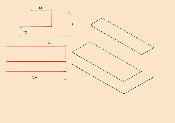
There are two common techniques generally used for isometric drawings. These are the box and the centerline layouttechniques. The box technique is the most common construction technique also known as the coordinate technique. In the approach, a bounding B- box is first made with guide lines using the principal dimensions object. The principal dimensions may be designated as W for width, H for height, and D for depth. It may be necessary to add up dimensions along the principal axes to get the principal dimensions of an object. The faces on the objects are then created after the B-box is ready. Each feature on the object is properly located and created within the B-box. This technique is good for drawing objects with angular and radial features or objects that have irregular shapes or form.
Box layout technique
The box technique will be used to create isometric views of different typical objects as illustrations. These include objects with normal faces, inclined faces, oblique faces, and irregular curves and isocircles.
To create a cube applying the box technique, use the reference drawing of the object in order to obtain the designated dimension of the object in isometric. Next, is to construct the isometric axes using parallel rulers.
On a new vector layer, select Rulers on the tool tab. In its sub category, select Special ruler. Next, in the special ruler’s tool property, choose Parallel line in the drop–down list. Set the rotation of the angle to 30 by checking the Step of angle and using the slider. Setting the rotation of angle to 30 equates to setting the ruler to 30 degrees to the horizontal when drawing.
Click and drag the mouse vertically on the canvas. A set of 3 parallel rulers is drawn, and a ruler icon appears beside the active layer's thumbnail. Place the mouse cursor right and at lower position of the vertical rulers, then click and drag at an angle to the left side of the vertical rulers. Automatically, another set of 3 parallel rulers is drawn at 30 degrees. Following the same procedure, repeat for the right receding axes making sure that the set of 3 parallel rulers intersect with the vertical and left receding axes though optional. A third set of 3 parallel rulers is drawn to the right at an angle.
Next, use the pen tool set to black and draw a vertical line which automatically follows the orientation of the set of vertical parallel rulers that is blue and active. The other two sets of parallel rulers are green and inactive.
To make a set of parallel rulers active, make sure the layer having the ruler icon beside the layer’s thumbnail is active or selected. On the tools tab, select the operation tool and object is selected in the sub tool category. Click on the inactive ruler. These small blue icons appear. Hover the mouse on them. The one that changes the mouse cursor to a touch icon is clicked. The set of parallel rulers turns blue and active.
Use the procedure above to complete the drawing of the isometric axes using the pen tool.
Next, click on the reference drawing layer. Then, select the reference drawing using the selection tool. Click on Rotate/Scale of the sub tool selection. In the selection tool property, use the rotate of angle slider tweaking the value to 30. Click OK.
The reference drawing is rotated matching the left receding axis of the three principal axis. Adjust the reference drawing such that its base is aligned to the base of the left receding axis and height aligned to the vertical axis. Making sure the set of vertical rulers is active, define the dimension of the cube’s width by drawing a vertical line at the receding point of the reference object. Complete the front plane by making the left parallel rulers active and defining the height of the cube from the height of the reference drawing close to the viewer parallel to the base of the reference drawing.
On the reference drawing layer, use the selection tool and select the drawing. In the selection sub tool, click the Rotate/ Scale tool. In the selection tool property, tweak the value of the rotation angle to -60. The base of the drawing is then aligned to the base of the right receding axis and its height to the vertical axis.
Activate the vertical rulers, then draw a vertical line defining the depth of the cube; then for the height, activate the right receding axes and complete the side plane of the cube drawing a line parallel to the base of the drawing.
For the top plane, draw a line parallel to the top of the side plane from the receding point of the top front plane. From the receding point of the top side plane, draw another line parallel to the left receding axis.
Erase unwanted projection lines. The cube in isometric is now complete.
The multiview reference of object's dimensions with normal faces are composed of straight lines showing the side and front views respectively.
To create the object with normal faces, the procedure in drawing a cube above is followed to draw object using the box technique.
The features of the object is then constructed defining the fraction of the object's height, H1 of the front and side planes. To obtain the fraction of the object's depth, D1, the side reference drawing is offset making the top align with the right receding axis.
Erase portions of the box to bring out the figure of the object.
The multiview reference of object's dimensions with inclined faces are composed of non-isometric lines showing the top and front views respectively. In the front view, the line that joins the points W1 and H1 is at an angle, hence, non - parallel to the isometric axes.
To create the object with inclined faces, the procedure in drawing a cube above is followed in drawing the object using the box technique. The top view reference drawing is rotated at 60 degrees to the horizontal aligning its depth to the right receding axis to create the box.
To create the features of the object, the top view is selected and rotated, this time to a value of -60 using the slider of Rotation of angle in the selection tool property.
From the reference drawing, the set of parallel rulers are drawn linking the two points; W1 and H1. Additional set of parallel rulers is drawn. This time, Step of angle is unchecked to give freedom of drawing the rulers in any direction of choice. Use the pen tool to draw the non-isometric line on the front plane of the object and another one opposite to it from the receding point of the side plane.
Erase portions of the box to bring out the figure of the object.

The multiview reference of object's dimensions with oblique faces are composed of sets of non-isometric lines showing the top and front views respectively. In the front view, the line that joins the points; W1 and H1 is at an angle, hence, non - parallel to the isometric axes. In the top view, another non-isometric line with a different angle joins the points; W1 and D1. Consequently, a third non-isometric view at the side plane of the imagined object will join the points H1 from the front view and D1 of the top view.
To create the object with an oblique face, the procedure in drawing a cube above is followed in drawing the object using the box technique and alignment of the views on the isometric axis is followed in previous isometric drawing types.
To draw the features of the object, the base of the reference drawing is adjusted such that fraction of the width, W1 is aligned to the left receding axis to obtain a vertical segment along the front plane of the box.
In addition, three sets of parallel rulers owing to unchecked Rotation of angle are drawn in respect to the reference drawings in order to obtain the dimensions of the oblique object. Use the pen tool to draw the non-isometric lines on the front, side, and top planes of the object.
Erase portions of the box to bring out the figure of the oblique object.

Here is the multi view of an object with angled faces. The width of the object in the front view is seen to move upward at 30 degrees to a point at the mid of depth of the object in the top view.
To create the objects with angled faces, the procedure in drawing the cube above is followed in drawing the box and alignment of the views on the isometric axes is followed as in previous isometric drawing types.
In drawing the features of the object, the top reference drawing is positioned such that the depth is aligned to the receding top edge same direction as the left receding axis of the box to obtain the midpoint of the box.
To achieve segments of the three planes, the front reference drawing is readjusted such that the top is aligned to the left receding axis to obtain the midpoint of the box on the front plane.
Here, the ruler icon is temporarily removed by dragging it to another inactive layer. Four linear rulers are used to achieve clean linear lineworks without confusion.
Trace the rulers to complete the features of the angled object using the pen tool.
Erase any un wanted projection lines to reveal the object.

Here is the multi view of an object with ellipse as the top view. The front view reference shows the non-isometric line connecting the overall height of the object, H at one end to a fraction of the overall height, H1. The ellipse has a diameter equivalent to the depth, D of the object.
To create the object with ellipse on an inclined plane, the procedure in drawing the cube above is followed in drawing the box of the object. The alignment of the front view on the left receding axis is followed as in the previous isometric drawing types.
After employing a set of rulers with free rotation angle and using the pen tool to draw the non-isometric lines.
Draw another set of rulers with free rotation angle diagonally along the inclined face of the object and draw a diagonal line.
The drawn vertical line along the vertical axis already completes the other diagonal on the inclined face.
Draw another line cutting through the middle of the inclined face. With the aid of the right receding rulers complete the grid on the inclined face.
Hide the drawing layer’s ruler by right-clicking on the ruler icon and choosing the checked show ruler in the fly out list.
In the tools tab, select figure and in the sub tool, choose curve. You can adjust the brush size in the tool’s properly so as to match the G-pen brush size.
Click and drag the mouse placed on the mid edge of the inclined plane to the next mid edge and release the mouse button. Pull the mouse such that the plus icon is taken to the edge of the face that connects the two mid edges.
Repeat the same process with other mid edges on the inclined face until an ellipse is created.
Still with the aid of the right receding rulers, draw two parallel lines each connecting the pair of points of intersection between the ellipse and the diagonal lines.
Switching to the vertical rulers, draw two vertical lines downwards from the initial points of intersections above.
Making the left and right receding rulers active one at a time, draw two parallel lines to complete the base of the object.
Draw a grid on the base of the object in addition using horizontal set of rulers as well.
Displace the drawing layer’s ruler once again and employ concentric circle ruler in the special ruler list.
Place the cursor at the mid of the base grid and click and drag out until the ring of the initializing ruler is touching the inner 4 points of the quadrant, then release the mouse button.
Use the pen tool and trace the rulers making sure it touches the four points. Draw two vertical lines to define the sides of the cylinder.
Then, erase unnecessary projection lines to make the object stand out.

Hope this technique will be useful to you. Thanks for reading!









Comment